Richard VA7RLW
Introduction
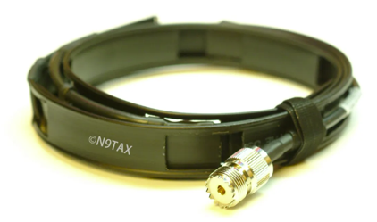
Having a portable VHF/UHF antenna in your kit for field use can be very handy. The classic model is the roll-up Slim-Jim (J-Pole) design using 450Ω ladder-line wire. They are portable … but a little cumbersome.
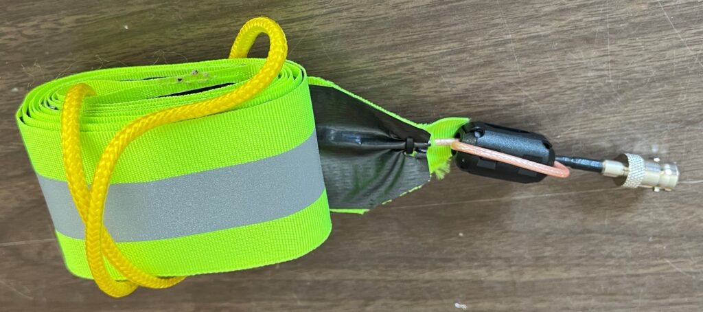
An improved design is based on placing Faraday tape on reflective cloth tape.
Theory of Operation
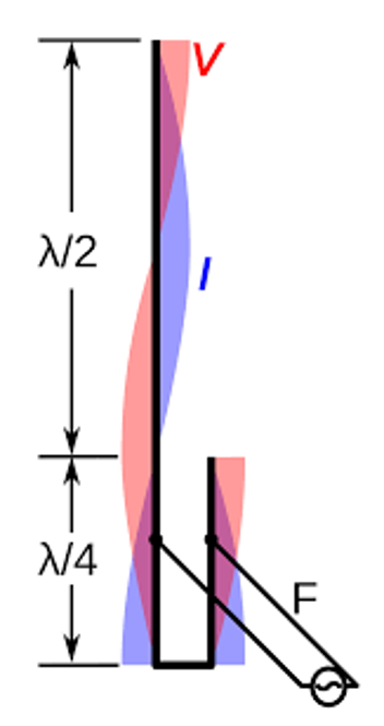
The J-Pole antenna was invented by Hans Beggerow in 1909 for use in Zeppelin airships.
This diagram illustrates the voltage and current distribution.
The bottom section is the tuning stub is used to ensure proper SWR.
The “Slim-Jim” design folds the upper portion of the antenna onto itself shortening its overall length
Components
All of the components are inexpensive and easy to obtain from your local hardware store, Amazon and other on-line stores.

Duct Tape – Be sure to get the “All Weather” version.
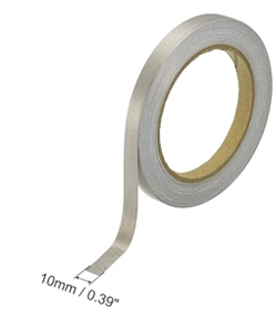
Faraday Tape – 10mm
NOTE: Faraday Tape is adverstised as a conductive material than can be used to isolate devices by blocking the frequency rane of most mobile devices and electronics that transmit/operate within.
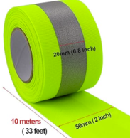
Reflective Cloth Tape
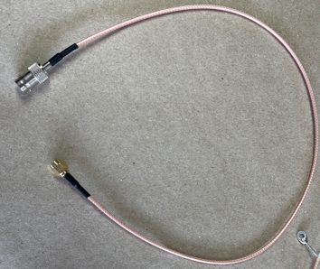
RG-316 20″ BNC-female to SMA-male pigtail
Nylon Rope
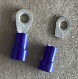
Terminal Rings

Snap-On Ferrite Choke 3mm
Wire Ties (small)
Tools
•Exacto knife
•Scissors
•Measuring Tape
•Sharpie (felt tip marker)
•Volt-Ohm Meter (preferably with audible tone for conductivity testing)
•Soldering iron
•Cutters (wire and snipping)
•Glue (preferably for cloth or Super Glue – but not epoxy)
Cable Assembly
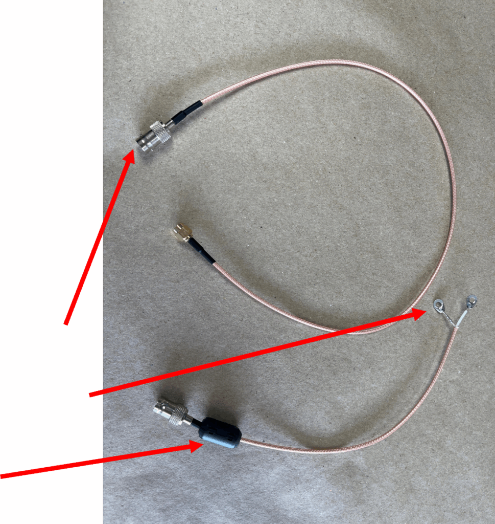
• You can terminate the cable with your choice of connector, but I narrowed the design to either a female BNC or male SMA by cutting the pre-assembled cable either in half or cut off the unwanted connector
• These are smaller and more portable compared to a female UHF connector
• SMA male is common for direct connect to VHF handhelds such as Kenwood, Icom, etc.
• I prefer the female BNC and use a short pigtail adapter for either direct connect to the handheld radio or to a coax extension cable
• Terminate the other end using the cut-off ring terminals and solder them to the separated inner and braided shield wires of the RG-316
•Attach the snap-on ferrite choke near the connector
Critical Dimensions
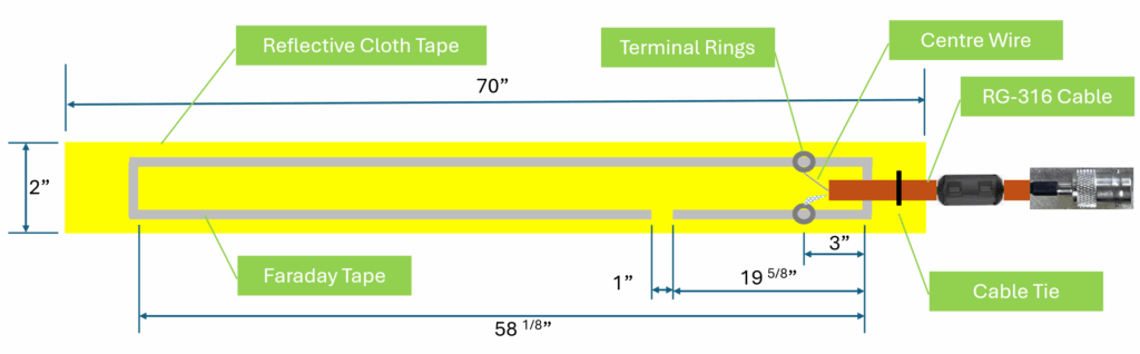
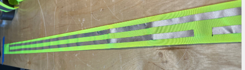
Faraday Tape Placement
•Lay the reflective cloth tape on a table and secure both ends using masking tape
•Mark the length as per the previous slide and carefully lay down the Faraday tape onto the reflective cloth tape
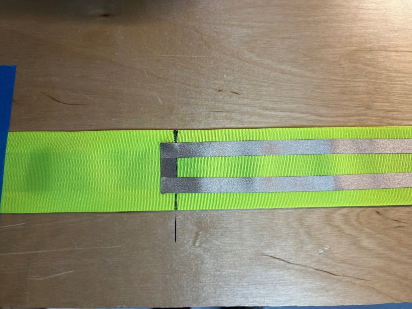
•Make sure to lay the Faraday tape onto each other to ensure conductivity
•You can check conductivity using a multi-meter
•Cut out the unused section
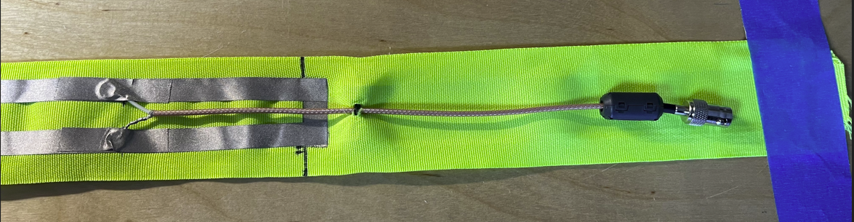
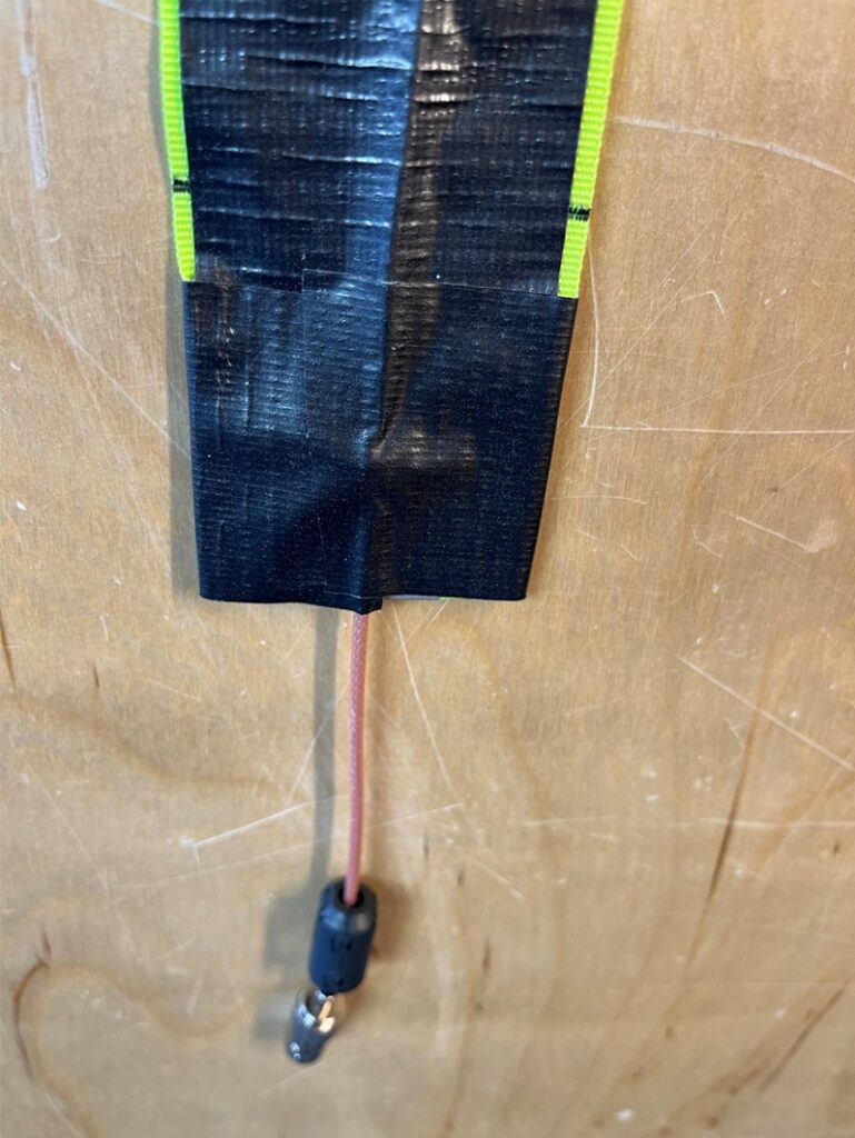
Cable Placement
•Lay the two rings of the assembled cable onto the contact points as per the “Critical Dimensions” diagram
•Use additional Faraday tape to hold the rings in position
•Use a wire tie wrap to secure the RG-316 coax onto the reflective cloth tape
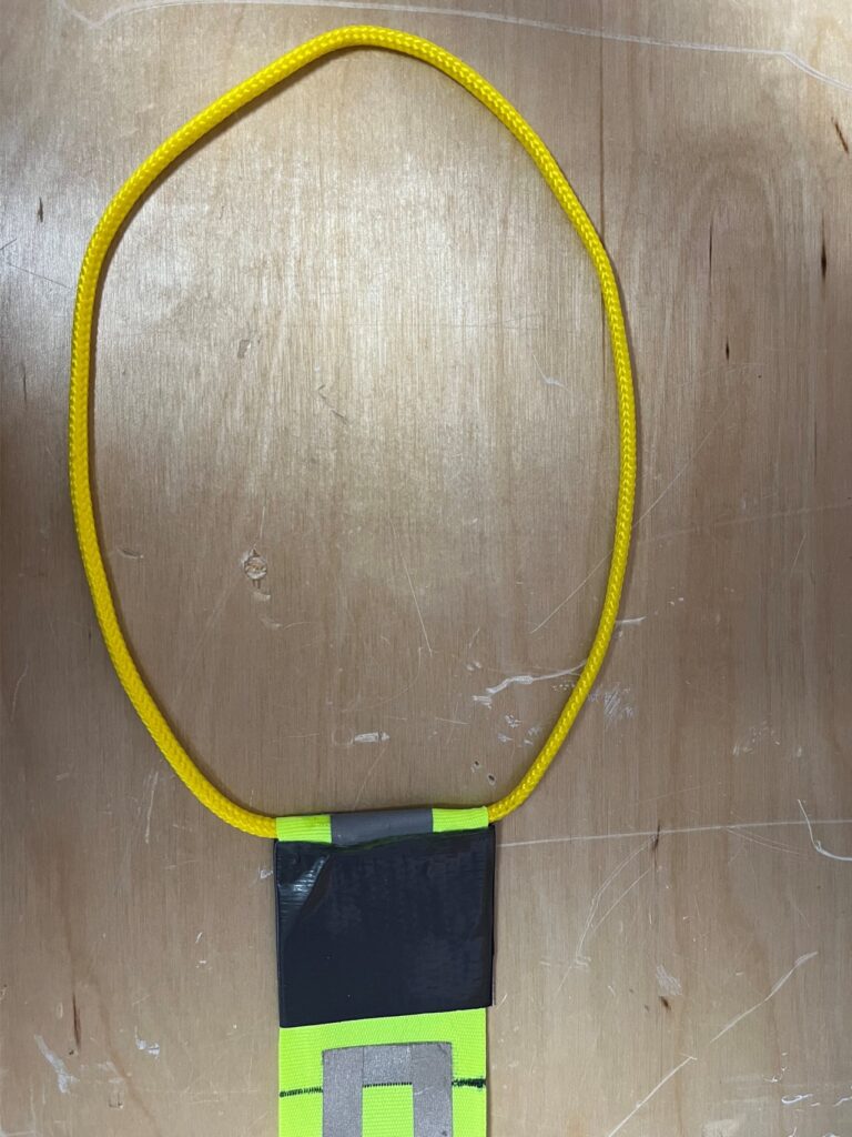
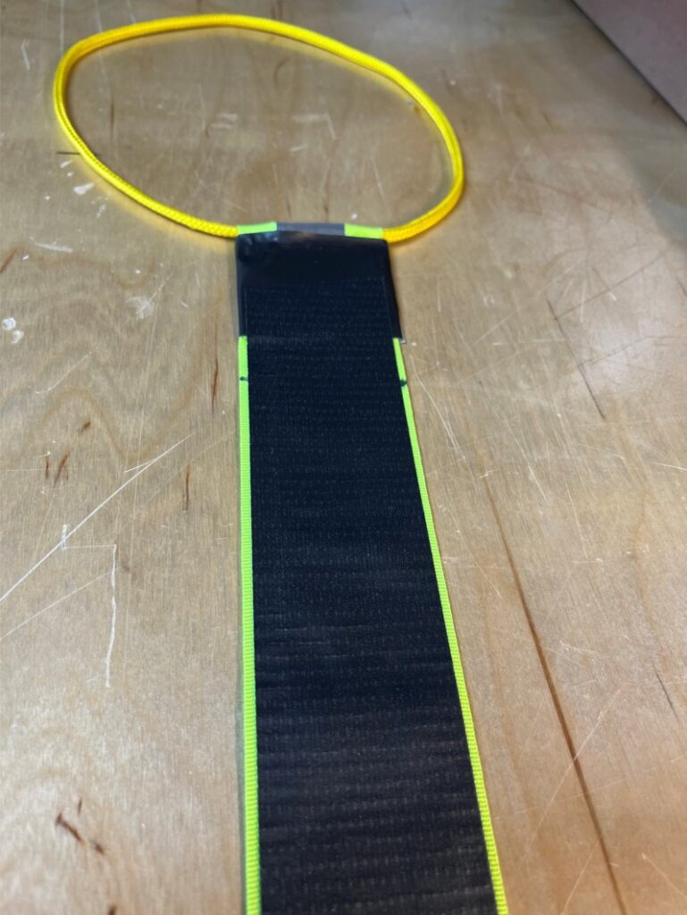
Prepare for SWR Check
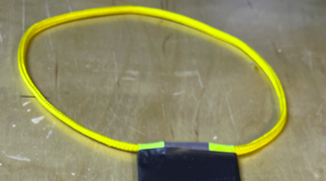
•At this point, assemble the top end with the rope in order to hang-up the antenna for an SWR check
•Cut a length of the nylon rope and melt the ends together
•Put the loop on the top end of the assembly, fold the extra length of reflective tape over the rope and onto itself and use glue and duct tape to secure the ends together
•You can sew the reflective cloth tape together if you desire – your choice
•Hang the antenna somewhere where there is no metal
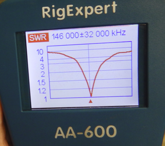
•Use an antenna analyzer to check for SWR
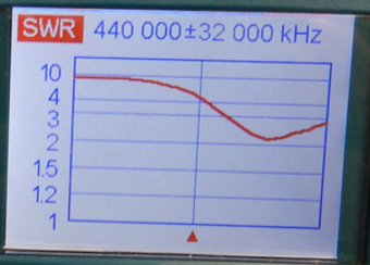
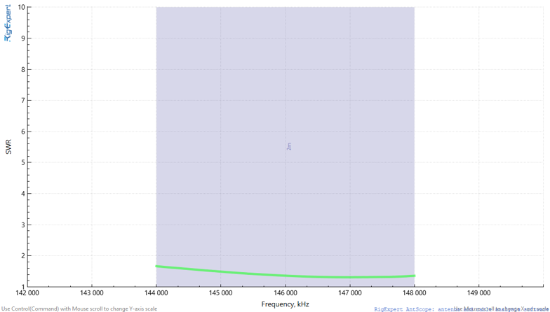
Antenna Analyzer | SWR
The antenna should tune well in the 2m band. Not as well in the 7cm band – but it is useable.
Final Assembly
If the antenna needs adjustment, then either lengthen or shorten the Faraday tape or reposition the ring terminals to ensure minimum SWR between 144 and 148 MHz.
If the antenna tunes, then it is time to use duct tape to seal up the side with the Faraday tape.
Use a plastic spreader to ensure an even application of duct tape across its entire length (no bubbles).
NOTE: If you have a sewing machine, you can sew the Faraday tape onto the reflector cloth tape – but hey, let’s be Canadian eh!